Formidable Info About What Happens To Potential Difference In A Parallel Circuit

Understanding Potential Difference in Parallel Circuits
Ever wondered what makes your house's electrical system tick? Or why you can plug in multiple devices without blowing a fuse (most of the time, anyway)? A big part of the answer lies in parallel circuits and how potential difference, also known as voltage, behaves within them. Let's dive in, shall we? Think of voltage as the "electrical pressure" that pushes current (electrons) through a circuit. It's what makes your lights light up and your toaster toast.
Now, imagine a water pipe splitting into multiple smaller pipes, all leading back to a central drain. That's kind of what a parallel circuit is like. Instead of water flowing, it's electricity, and instead of pipes, it's wires or conductors. The critical thing to remember is that each of those smaller pipes (or branches) has the same water pressure (or voltage) as the main pipe. Makes sense, right?
Parallel circuits are designed so that each component (like a light bulb or an appliance) gets the full voltage it needs to operate correctly. Thats why you can turn on your TV and your refrigerator at the same time without one affecting the other (unless, of course, you overload the circuit, but we'll get to that later). This "constant voltage" aspect is what defines a parallel circuit and makes it so useful in our everyday lives.
So, what happens to the potential difference — that's our keyword here — in a parallel circuit? Well, it remains the same across all branches. Yes, it's that simple! This uniformity is crucial for the functionality of the devices connected in parallel, ensuring they all receive the required power without interference. Its the electrical equivalent of everyone at a pizza party getting their fair share.
1. Why Constant Voltage Matters
Think about it: if the voltage dropped significantly at each appliance, your lights would dim, your TV would flicker, and your toaster might just decide it's not in the mood to toast. Not ideal, is it? This constant voltage is what allows independent operation of each device connected to the circuit. Each branch acts like it's the only one in the system.
This is why parallel circuits are used in most household wiring. Each outlet provides the same 120V (in North America) or 230V (in Europe) to whatever you plug into it. This allows you to use any appliance in any outlet without worrying about voltage fluctuations affecting its performance. The key is to keep the overall current draw within the circuit's capacity to prevent overloads.
This design contrasts sharply with series circuits, where voltage is divided among the components. If you've ever seen Christmas lights where one burned-out bulb takes out the entire string, you've witnessed the downside of a series circuit. With parallel circuits, one faulty device doesn't affect the others. It's a much more robust and reliable design for everyday use.
Consider a scenario with three light bulbs connected in parallel. Each bulb is designed to operate at 12V. In a parallel circuit, each bulb receives the full 12V, ensuring they all shine brightly. If one bulb burns out, the other two continue to illuminate without any change in brightness. The constant voltage is what keeps everything humming along smoothly.

Parallel vs. Series
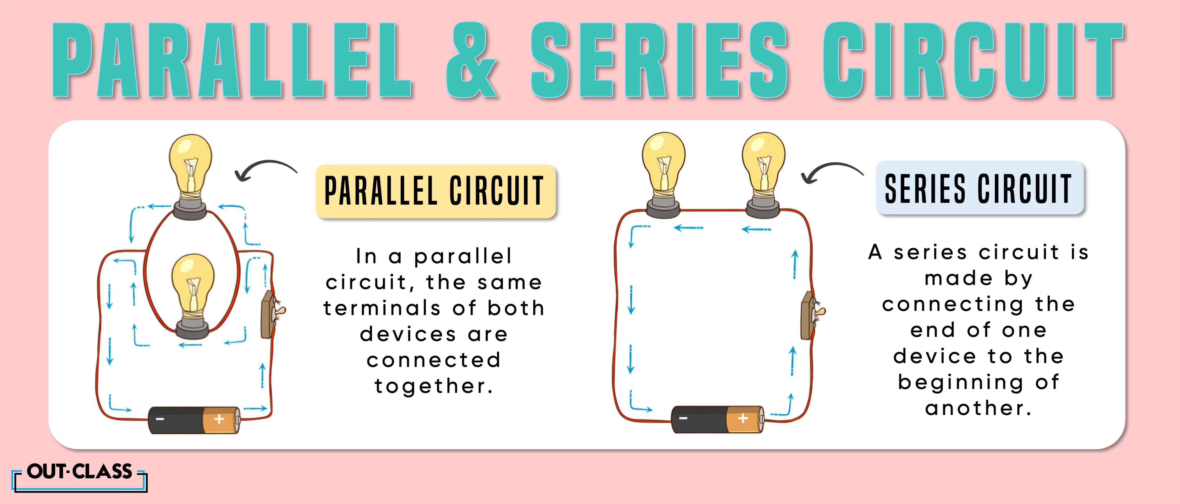
To further solidify your understanding, let's quickly compare parallel and series circuits. In a series circuit, components are connected one after the other, forming a single path for the current. The potential difference (voltage) is divided among the components, and if one component fails, the entire circuit breaks.
In contrast, parallel circuits provide multiple paths for the current. The potential difference is the same across all branches, and if one branch fails, the others continue to operate. This difference in behavior makes parallel circuits far more practical for most applications where independent operation of multiple devices is required. You can think of it like a highway with multiple lanes vs. a single-lane road — one breakdown on the highway doesn't stop everyone.
Another key difference is the way resistance is handled. In a series circuit, the total resistance is the sum of the individual resistances. In a parallel circuit, the total resistance is lower than the resistance of the smallest resistor. This means that adding more components in parallel increases the total current drawn from the source.
Understanding these differences is essential for anyone working with electrical circuits. Whether you're troubleshooting a faulty appliance or designing a complex electronic system, knowing how voltage and current behave in series and parallel circuits is fundamental. It's the difference between building a functional system and creating a potential fire hazard!
2. Calculating Voltage in Parallel Circuits
While the voltage is the same across each branch, its still useful to understand how to calculate other aspects of a parallel circuit. Ohm's Law (V = IR) is your best friend here. This simple equation relates voltage (V), current (I), and resistance (R).
Since the voltage is constant, you can use Ohm's Law to calculate the current flowing through each branch if you know the resistance of that branch. You can also calculate the total current drawn from the source by summing the currents in each branch. This is important for ensuring that the circuit doesn't exceed its current capacity.
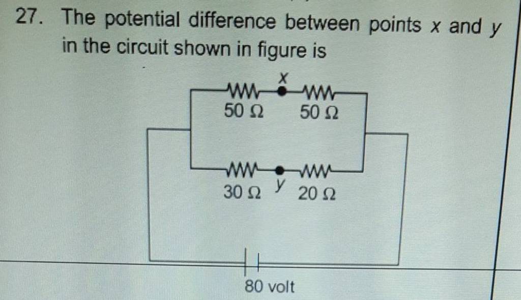
For example, if you have a 120V circuit with two appliances connected in parallel — one with a resistance of 20 ohms and the other with a resistance of 30 ohms — you can calculate the current through each appliance: I1 = 120V / 20 ohms = 6 amps, and I2 = 120V / 30 ohms = 4 amps. The total current drawn from the source is 6 amps + 4 amps = 10 amps.
Knowing how to perform these calculations is crucial for designing safe and efficient electrical systems. It allows you to choose the appropriate wire gauge, circuit breakers, and other components to prevent overloads and ensure reliable operation. Its like knowing the recipe for a cake — you need the right ingredients in the right proportions to get the desired result.

Series And Parallel Circuits Potential Differences Circuit Diagram
Practical Applications of Parallel Circuits
Parallel circuits are ubiquitous in modern electrical systems. From household wiring to complex electronic devices, they are used in countless applications. Their ability to provide constant voltage to multiple components makes them indispensable.
In homes, parallel circuits ensure that each outlet provides the same voltage, allowing you to plug in any appliance without affecting the others. In cars, they power various electrical components, such as headlights, taillights, and the radio. In computers, they distribute power to different components, such as the CPU, RAM, and hard drive.
Even in large-scale power distribution networks, parallel circuits play a crucial role. They allow power companies to deliver electricity to multiple customers simultaneously without voltage drops. This ensures that everyone gets the power they need, when they need it.
Consider the lighting system in a large office building. Each light fixture is connected in parallel, ensuring that all lights receive the same voltage. If one light bulb burns out, the others continue to illuminate without any interruption. This is just one example of how parallel circuits make our lives easier and more convenient. They are truly the unsung heroes of the electrical world. It is good to mention the phrase potential difference here.
3. Troubleshooting Common Parallel Circuit Issues
While parallel circuits are generally reliable, they can sometimes experience problems. The most common issue is overloading, which occurs when the total current drawn from the source exceeds the circuit's capacity. This can trip a circuit breaker or blow a fuse, cutting off power to the circuit.
Another common problem is short circuits, which occur when a low-resistance path is created between two points in the circuit. This can cause a large current to flow, potentially damaging components and creating a fire hazard. Identifying and repairing short circuits requires careful troubleshooting and a good understanding of electrical principles.
To prevent overloading, it's important to calculate the total current drawn by all devices connected to the circuit and ensure that it doesn't exceed the circuit's rating. To prevent short circuits, it's important to use properly insulated wires and connectors and to inspect the circuit regularly for any signs of damage. Regular maintenance can go a long way in preventing problems and ensuring the safe operation of parallel circuits. That potential difference matters a lot here.
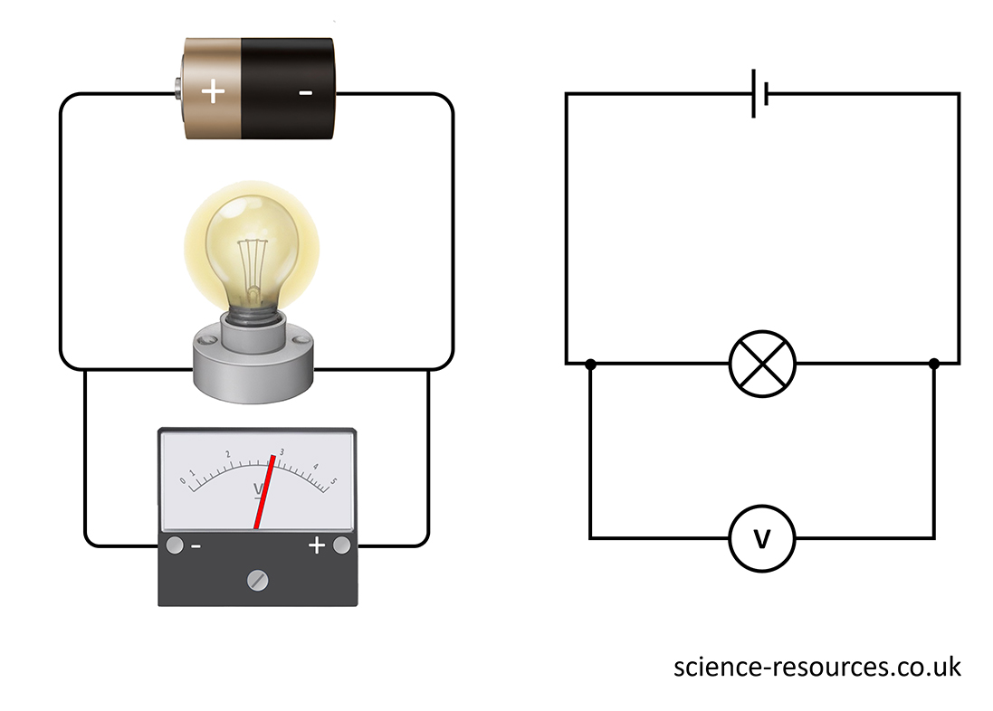
When troubleshooting parallel circuits, it's helpful to use a multimeter to measure voltage, current, and resistance. This can help you identify the source of the problem and determine the best course of action. With a little knowledge and the right tools, you can diagnose and repair most common parallel circuit issues.

FAQs About Potential Difference in Parallel Circuits
Still got questions? No problem! Let's tackle some frequently asked questions about potential difference in parallel circuits.
4. Q
A: The current divides among the different branches of a parallel circuit. The amount of current flowing through each branch depends on the resistance of that branch. Branches with lower resistance will have higher current, and vice versa. The total current flowing from the source is the sum of the currents in all the branches.
5. Q
A: The main advantage is that each component receives the same voltage, regardless of how many other components are connected. This allows for independent operation and ensures that each component functions properly. Also, if one component fails, the others continue to operate. Very useful when the goal is a stable potential difference!
6. Q
A: The formula for calculating the total resistance (Rtotal) in a parallel circuit with two resistors (R1 and R2) is: 1/Rtotal = 1/R1 + 1/R2. For more than two resistors, you simply add the reciprocals of all the resistances and then take the reciprocal of the result. The total resistance in a parallel circuit is always less than the smallest individual resistance.

